calibration
for digital recorders corresponding to IEC 1083-1
calibration of impulse measuring systems corresponding to IEC 60-2
calibration
|
calibration
for digital recorders corresponding to IEC 1083-1 |
|
|
calibration of impulse measuring systems corresponding to IEC 60-2 |
|
The
descriped programs TRAS-KAL and TRAS-TEIL don’t belong to the usual delivery
of the software. If you have interests or need this parts of the software, you
can purchase them if you contact the manufacturer or your appropiate
representative.
For measurements or calibrations corresponding to IEC 1083-1 or IEC 60-2 you
will need high-precision calibration-generators, which as far as possible should
be adjusted to the digital-measuring system you want to calibrate. For this
assignment there was developed a
whole family of new calibration-generators including the necessary software,
which give you the ability to practice all claimed calibrations or measurements
corresponding to IEC 1083-1 and IEC 60-2.
The impulse calibration system KAL 1000 is a
modular system to calibrate impulse measurement systems for highvoltage-test
technique. The modular assembly of the system makes it possible to to
build an optimal KAL-configuration from your defined needs.
The modularity allows to extend or
reconfigure your KAL-system by growing or changing requirements. The technical
design of the impulse-calibration system KAL 1000 considers the international
standard IEC 1083-1, digital recorders for impulse voltage and
current-measurements and the expected decision of the standard IEC 60-2 which is
currently in revision.
|
calibration of digital recorders corresponding to IEC 1083-1 |
The calibration of several measuring ranges of digital impulse measurement systems TR-AS 25/8/10/12 or TR-AS 100/200.8/10/12 corresponding to IEC 1083-1 as “performance check”can either be done with an impulse-calibration or alternative with an extra calibration of voltage and time via step-voltage.
|
calibration
software TRAS-KAL |
The
automatic control of impulse-calibration-systems is done via a coaxial
connection which is connected to the calibration-relay of the digital impulse
measurement system TR-AS.
The channels which you should be calibrated will be connected either alone or in
parallel to the output of the calibration-generator.
ATTENTION : Only
connect outputs while dead.
The maximum deviation and the mean-value of the choosen records will be saved
into a protocol-file from which can be made the calibration-certificate later.
The base-device consists of a electronical controlled highvoltage loading
device, which loads the output stage of the calibration-generator. The
output-voltage can be set in a high-precision range between 0V and 1000V. The
output of the base-device is a coaxial jack and there are two additional
measurement jacks from which you can measure the output-voltage via an external
high-precision voltage instrument.
Because of this there is the ability to back-annotate the measurements to a
calibration-laboratory or the PTB (Physikalisch-Technische Bundesanstalt).
At
the beginning of the automatic calibration-sequence, you must input the choosen
value of the loading direct-voltage. This value is the reference for further
calculations in the calibration process.
 |
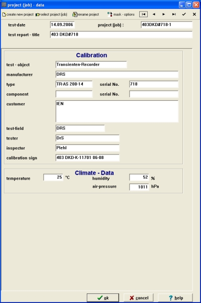
There
must be now an input-dialogue. In this dialogue you can select or create a new
project / job. In this case there is no need to select a test-setup,
display-view or recorder-setting.
Data, which describe the test-object like serial-no., date etc. can be input in
this dialogue.
 |
calibration-type and calibration-profile
 |
Here
you can select the used calibrator-type KAL 1000 and as profile-name the
serial-no. of the used calibration-generator. The input “KAL 1000” without
serial-no. defines a calibrator with standard parameters corresponding to IEC
1082-1. In “calibration-profile” you can input calibration-results of a
calibration-generator. In dependence to the serial-no. e.g. KAL1000#190 you can
additional select the calibrator-settings.
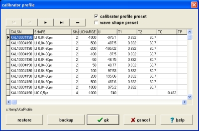 |
Creation
of a calibration-profile
For each
calibration-generator should be generated an own profile. For input of data you
must first select the profile-name. We recommend to use the DKD-calibration
protocol to create a profile and to use as profile-name the “KAL1000”+serial
no. or “DKD”+calibration no.
For each impulse wave-shape you must input the load-voltage and the
corresponding standard values from the calibration-protocol, where the data in
rows with “+” must be input.
impulse
and measuring input
The wave shape and the meas
start of the calibration / measurement range
 |
After
starting the calibration with “F8” or the corresponding toolbar button,
there must be made some settings. The recorder can be calibrated in the
measurement ranges with reference to the borders for voltage-range which are
described in the calibration-certificate from KAL 1000. The measurement ranges
which should be calibrated, can be selected after start of calibration in the
follwing dialogue.
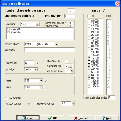 |
impuls-calibration
The impulse calibration is done with the impulse-calibration generator KAL-LI
0,84/60 (optional with KAL-LI 1,56/60) for full or chopped lightning-impulse
waveform or with impulse-calibration generator KAL-SI 20/4000 (optional with
KAL-SI 250/2500) for full or chopped switching impulse waveform. The
corresponding wave shape must be selected.
connection KAL 1000-LI and –SI
If you are using a positive impulse-voltage, there must be connected a
short-circuit plug to the negative BNC-output jack. The positive BNC-output jack
for LI or SI will be connected via a coaxial connection cable with the inputs of
the digital impulse-measuring system which you want to calibrate.
ATTENTION: Only connect outputs while dead.
The
voltage impulse-load will be transferred internal.
The trigger-input of the base-device (firing input) will be connected via
coaxial connection cable with the control-relay output (control out) of the
digital impulse-measuring system.
The amount of the pre-calculated impulse-voltage load will be displayed.
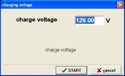 |
The
loading voltage must be chosen corresponding to the reference value at the KAL
1000 or the pre-calculated value of the measuring system must be edited if you
aren’t able to set the value at the KAL 1000.
The
record will be automatically started if you chosen “OK”, the calibration
generator will be triggered and the measured impulse will be evaluated until the
calibration of the measurement range is done (the amount of records you have
chosen in input-dialogue will be recorded).
calibration
with STEP-voltage
This calibration is done with step-voltage taken from the step-voltage generator
KAL-STEP. The wave shape STEP must be selected in this case.
connection
for KAL 1000-STEP
For negative STEP-voltage you must connect the BNC-output jack via a coaxial
connection cable with the impulse measuring system you want to calibrate.
ATTENTION: Only connect outputs will dead.
The triggering-input of the KAL 1000 base-device (firing input) must be
connected via coaxial connection cable with the control-relay output of the
digital impulse-measuring system. Further information is given in “impulse
calibration”
time
calibration
The time-calibration will be done with a built-in
high-precision timemark-generator. The wave shape TIME must be selected.
connection
for KAL 1000-TIME
For the time-calibration the BNC-output jack TIME must be connected via a
coaxial connection cable with the inputs of the digital impulse measuring
system.
The triggering-input of the KAL 1000 base-device (firing input) must be connected via coaxial connection cable with the control-relay output (control out) of the digital impulse-measuring system. Further information is given in “impulse calibration”
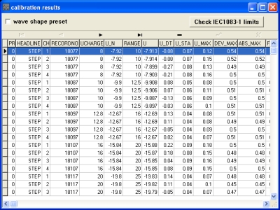
calibration
results
The
calibration results will be saved into the WinTRAS-internal database und can be
displayed in a result.list. The automatic IEC-check operation “CHECK IEC
1083-1” displays the maximum differences for each parameter filtered for the
actual wave shape.
calibration
protocol
 |
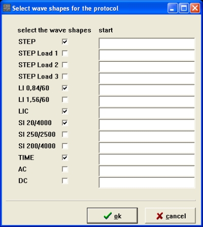
First
you can select the wave shapes you want to print.
 |
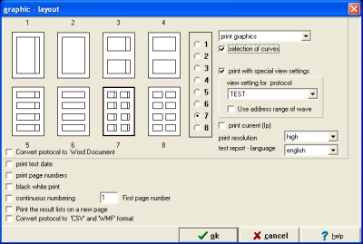
If
you have saved curves when you did your calibration, you can select the output
of this graphics and several other options in this dialogue.
The
output of the calibration results is done in tabular form beginning with the
test-object data and following the calibrated wave shapes (as you can see in the
small preview for the wave shape LI 0,84/60).
|
calibration
of impulse measuring systems corresponding to IEC 60-2 |
This
method is taken to determine the dynamical scale factors and the response
parameters of the whole measuring system. This is done with the standard-jump
method from IEC 60-2.
The
calibration of impulse measuring systems which consist of highvoltage-divider
with connection, measuring cables and digital impulse-voltage measuring system
TR-AS happens with the parameter-method taken with the rectangle-impulse
geneator KAL 1000-RIG and the calibration software TRAS-KAL.
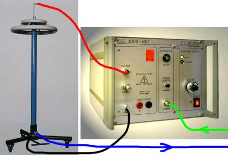 |
The
generator is placed at the floor or at one wall in the test-field. The generator
will be connected to the high-voltage divider and the measuring system as
described in IEC 60-2.
ATTENTION : Only connect outputs while dead.
If
you use positive impulse the negative BNC-output of the KAL 1000-RIG must be
connected with a BNC short-circuit plug. The positive BNC-output jack must be
connected with the high-voltage part of the divider (red). The ground must be
connected to the earth of the impulse-circuit at the high-voltage divider
(black).
The input for voltage-load must be connected when using a KAL 1000-RIG without
internal HV-device via coaxial cables using special high-voltage plugs with a
KAL 1000 base-device (not displayed).
The triggering-input must be connected using a coaxial cable (green) with the
control-relay output of the digital measuring system.
The measuring cable from the divider (blue) will be connected to channel 1,
input jack 10V of the digital measuring system.
|
Performance
check |
The parameter method used in “performance check” corresponding to IEC 60-2 measures amd evaluates the response to a dirac-impulse and from this the method can directly determine the dynamic scale factor and time-parameters. This values can be compared to data from the manufacturer or former as “performance tests” accomplished measurements.
|
Calibration
software TRAS-TEIL |
For
the partly automated calibration and the full-autoamted creation of
calibration-certificates there is the efficient software TRAS-TEIL at disposal,
which has a user-friendly menu guidance.
The determination of dynamic scale factors and response parameters of the
overall system corresponding to IEC 60-2 takes the rectangle-impulse generator
KAL-RIG and uses a repetitive sampling-method, which enables sampling-rates
between 1 and 5 GHz with the digital recorders TRAS 100/200-8/10/12. This method
is built into the calibration software TRAS-TEIL.
The automated control of impuls-calibration systems is done with the help of
a digital impulse-measuring system TR-AS with built-in or additional
control-relay.
In
this case firstly the response g(t) of the impulse-measuring system is
determined, while a sampling-factor of 10 when using 200 MS/s and/or 20 when
using 100 MS/s sampling-frequency corresponds to a total sampling-frequency of 2
GHz (this is a time-resolution of 500 ps). This method gives very good accuracy
while short test-time.
|
Options |
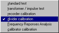 |
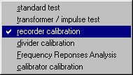
Application
„divider calibration“ should be chosen. Please select or create a
project/job and input the relevant data for the test-object. As
test-setup there will be automatically chosen „REP“ from the software.
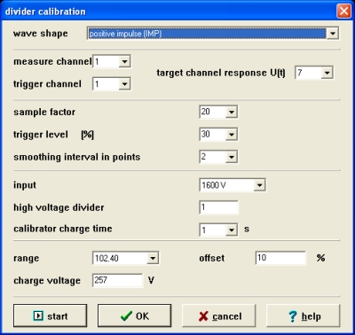 |
- choose
measuring and triggering channel with channel 1
- choose target channel with channel 7
-
choose
as input range either 10V or 1600V according to the magnitude
of response you expect due to the divider-ratio
- choose
trigger-level in the middle of the linear rise of the impulse you want to
measure
- Input
the divider-ratio of your high-voltage divider
- Measuring
range : this should be approximately 150 % of the voltage-load
in dependence of the overshot of your divider
- Zero-line
: approximately 10% when using positive impulse and 90% when using negative
impulse
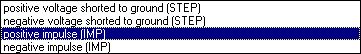 |
- select
wave shape
- Consider
that KAL 1000 is providing a positive voltage which is shorten (=STEP)
- Consider
that RIG 1000 is providing a positive or negative voltage which is an impulse
(=IMP)
With
„START“ the automatic determination of the response is started.
|
Evaluation |
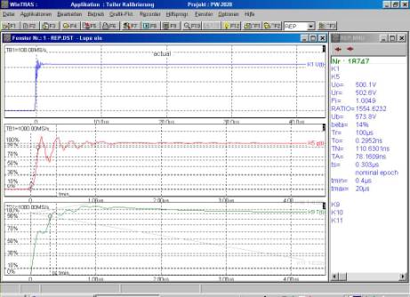 |
In
the form „eveluation“ there must be displayed the evaluation type „RESP“
in channel 7. The calculation of „response paramters“ from response g(t) and
the time-process for response time T(t) is done as integral of the function „
1 – g(t) “ automatically through internal computer of the measuring system.
Resp - impulse response evaluation
The evaluation pf the response time T(t) takes place between the selectable time-interval tmin and tmax| The culculate results: | |
| ß | overshot |
| Fi | scale factor calculated |
| Fe | determined scale factor , t --> end of measurment |
| O1 | virtual origin set to t=0 |
| To | initial distortion time |
| Ta | 1st. partial response time |
| TN | experimental response time in t= tmax |
| Te | experimental response time in t à meas.end |
| ts | settling time |
| tmin | begin of evaluation |
| tmax | end of evaluation |
You should take care of the calculation of
settling time ts because this is especially dependent of the choosen border
tmin. If tmin is chosen to small you will possibly get bigger settling times ts.
Result of the divider-calibration can also be taken as references. This
paramters can be taken for later „perfomance checks“ as comparison. If
displaying response parameters you can edit the border-values.
The DAC 16-card is used in one ISA-slot of the
measuring systems’s internal control-computer. It works with a resolution of
16 bit and outputs high-precision direct-voltages. There are two output-ranges :
-2 V ... +2 V and –10 V... + 10V
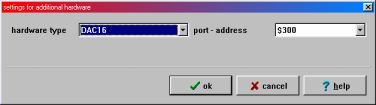 |
This additional hardware
must be configured
using the WinTRAS-configuration tool as displayed in following picture.
The output-voltage is available at the BNC-jack „DAC OUT“. The second BNC
jack " REL " is connected with a relay contact, which switches with
triggering after mass (here not used). The card can be taken to control the
voltage-load of the calibration generator KAL 1000.
For this purpose one connects the BNC bush " DAC OUT " and/or.
„U-Out "over the provided adaptor cable with the DB9-connector
"control" at the rear side of the calibration generator.
If
you want to trigger the calibration generator by software-control, you have to
connect the BNC jack „REL OUT“ of the measuring system via coaxial cable
with the jack „external trigger“ at the front panel of the KAL 1000.
 |
The control for voltage-load of the
calibration generator KAL 1000 is done full-automatic while calibrating with
calibration software TRAS-KAL.
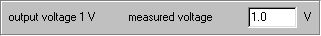
After start of calibration you have to input the measured voltage-load of KAL
1000 while output is 1V. This is done to compensate the small offset-error
of DAC 16.
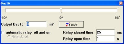 |
The voltage-load of the calibration generator can additional be controlled
by small tool „DAC 16-help“ which directly sets output-voltage of DAC
16-card.
In this case the dependence is :
- voltage-load KAL 1000 = Ua (DAC 16)*100
- display (as you can see in
picture above) corresponds to voltage-load of 387,5 V.
ATTENTION :
If you work with the KAL 1000-generator you should only set positive DAC
16-output voltages.
The high-precision voltage-output of the DAC 16-card and the control-input of
the high-voltage generator built-in KAL 1000 base-device is only conditionally
protected against overvoltages.
The use of this system can only be done if KAL
1000 is built into a shielded measuring rack MIRA 25.
With application in table housings DERA 6 and separate KAL 1000 this control
line as well as all other electrical connections (printers...) are to be removed
reciprocally, in order to prevent electrical influence or destruction from
measuring system or Kalibrator with impact tests.
For
such errors we cannot take over a guarantee!