frequency response analysis
| newest improvements and further informations |
Primary
the application "Frequency Response Analysis"
must be selected and project must be selected.
The now described software-package is not generally a part of the delivered (usual) WinTRAS-software. It can be ordered for demo-usuage or if needed at the manufacturer or one of its representatives.
With help of "frequency response analysis" you are able to determine the frequency-dependent conductance of test-object. This analysis should determine differences in electrical properties of the test-object before deliver, after transport or something else.
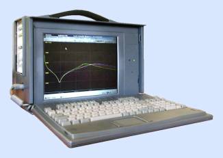
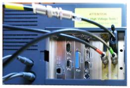
The
portable PC housing includes a digital recorder with 2 measuring channels TR-AS
25-12 with up to 25 MS/s sampling rate at 12 Bit resolution and a maximum input
voltage of 10 Volt. The measuring system is designed for low voltage impulse
measurements, there is no special shielding for H.V. Test Applications.
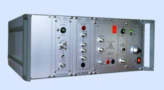
The
connection unit comprises
Ø
a STEP impulse
generator RIG 1000 with inbuilt h.v. loading circuit for exciting the test
object
Ø
a connection
unit FRA-CON for easy 2-pole connection of the test object
Ø
an impulse
measuring shunt of 1 Ohm for current measurements
Ø
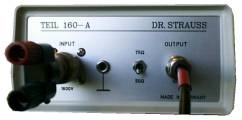
an active
voltage divider TEIL 160-A for measurement of the applied voltage
Ø
an external
active voltage divider TEIL 160-A for measurement of the adtransmitted voltage
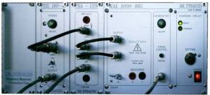
RIG
1000
IMP-OUT 1 kV red isolated wire to
phase under test
GROUND black
wire to ground of phase under test
+
Output
BNC FRA-CON
RIG +
- Output
BNC
RIG –
Firing Control BNC
TRAS
Control Output
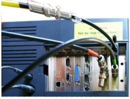
FRA-CON
u(t)
BNC TEIL160-A
1000 V input
TEIL160-A
Output 10 V BNC
TRAS
CH 1
FRA-CON i(t) BNC TRAS CH 2 (50 Ohm term.)
FRA-CON
u(t)
BNC TEIL160-A
1000 V input
TEIL160-A
Output 10 V BNC
TRAS
CH 1
TEIL160-A
INPUT 1000V
isolated wire to secondary phase
GROUND black
wire to ground of secondary phase
TEIL160-A
Output 10 V BNC
TRAS
CH 2
If application "frequency response analysis" is chosen, the menu-bar will occur automatically. This is the standard menu-bar with a additional button called "FRA.
|
|
|
TF = transfer function results of the source channels
|
Logo, Button |
definition |
|
|
start the FRA test sequence |
|
|
copy the TF measure channel 15 and 17 to compare channel 11 and 19 |
|
|
copy the TF measure channel 15 and 17 to compare channel 12 and 20 |
|
|
copy the TF measure channel 15 and 17 to compare channel 13 and 21 |
|
|
compare 3 phases |
|
|
calculate the 50 Hz (60Hz) admittance / impedance |
If you want to
change the settings of the frequency response analysis,
you must “right-click”
with mouse on the “FRA”-button from menubar.
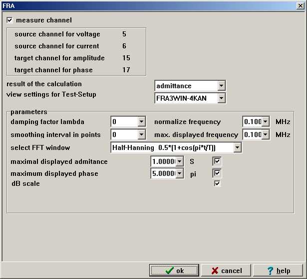 |
The following tables describes all possible options to change
| prompt | definition | default values |
| source channel voltage | channel in which voltage has been recorded | 5 |
| source channel current | channel in which current has been recorded | 6 |
| target channel amplitude | the amplitude result of the FRA calculations (admittance or impedance ...) | 15 |
| results of | ||
| target channel phase | the phase result of the FRA calculations | 16 |
| lambda optimizing | voltage-dependent damp for magnitude | 0 |
| normalize frequency | frequency window which is used for normalizing | 0.5 MHz |
| smoothing interval in points | data of impulse can be smoothed (filtered) with this option | 0 |
| select FFT window | window for boundary value correction | Half-Hanning. |
| maximal displayed frequency | maximum value of frequency-scale | 1.0 MHz |
| maximal displayed amplitude | it is possible to put in the maximum amplitude (admittance or impedances or Uin/Uout or Uout/Uin) | 1 S |
| maximum displayed phase | here you can select your preferred display-view | 5 pi |
| dB scale | use dB scale for amplitude values | selected |
| test - sequence |
The frequency response analysis must be used with the connection unit ( rectangular impulse-generator RIG) to analyze the test-object (in normal case a transformer).
As default test setup we have create:
FRA2-5 => sampling rate 2,5MS/s
FRA6-25 => sampling rate 6,25MS/s
Typically the customer test the following bushings.
| Pos. | voltage impulse | current answer | test setup |
| high voltage | |||
| 1 | 1W | 1N | FRA2-5 |
| 2 | 1V | 1N | FRA2-5 |
| 3 | 1U | 1N | FRA2-5 |
| low voltage | |||
| 4 | 2W | 2N | FRA2-5 |
| 5 | 2V | 2N | FRA2-5 |
| 6 | 2U | 2N | FRA2-5 |
| ratio | |||
| 7 | 1W | 2W | FRA2-5 |
| 8 | 1V | 2V | FRA2-5 |
| 9 | 1U | 2U | FRA2-5 |
| start
record |
The following dialog starts:
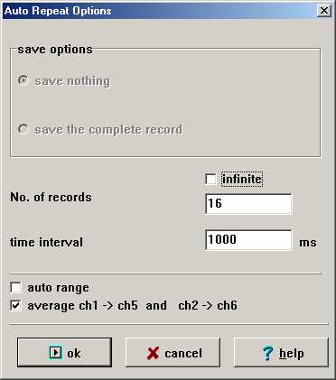
Description of the dialog:
| name | definition | default values |
| No. of records |
16 |
|
| time interval | is the time interval between the single shots |
1 |
| auto range | if auto range is on, the digitizer tries to find the optimal measure range | not selected |
| average Ch1->Ch5 and Ch2->Ch6
|
for a better result the system makes typically 16 (16=24 =>+4 Bit => the result signal has 16 Bits resolution) records and add each record. Wit this method we decrease the noise level of the signal. The average method delete the statistic noise. The result we copy to the virtual channels 5 and 6. Our experience shows that facto 16 is enough. |
selected |
If you select now the OK button the TR-AS makes a first control record. Is this impulse ok the system makes automatically 16 records and generates the virtual channels 5 and 6. From this both channels we calculate the admittance or the impedance depends on capture setup frequency analyze response parameters.