This menu provides all controls for the settings and the configuration of the installed digital recorder.
This
menu item executes all necessary setting
dialogs for the operation settings of
the digital recorder.
 |
The
controls of this dialog depend on the configured digital recorder.
Divergences
to the illustrated dialog are possible.
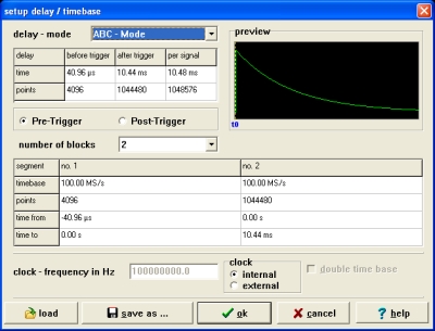
The onboard memory of the digital recorder
is divided into a specific number of memory segments which are also
called
memory blocks.
It depends on the recorder type if
the number of these blocks is fixed or if you have the
possibility to
change the number of blocks.
Recorder
with fixed number of blocks
This
recorder type has two, four or eight memory blocks. The block length is
also
fixed. The control „number of blocks“ is therefore disabled
and shows only
the number of memory blocks.
This recorder type allows you to change the delay – mode
(multi-signal or
single signal).
Recorder
with variable number of blocks
This
recorder type allows you to varied the number of memory blocks from two
to eight
blocks. It is also allowed to change the block length for each
configured block.
The length of the first block is the number of points before trigger
event in
pre – trigger mode. The delay – mode for this recorder type
is fixed (ABC
– Mode).
Attention:
To
operate this dialog do as follows:
Select the number of blocks. The table in the lower area of the dialog
will
change the number of columns if you change the number of blocks. Each
column
shows the data of a specific memory block.
Select for each block (segment) the
timebase and the number of points (=block length). Every change of one
of these
parameters will modify the time information in the last row of the
table. You
can change the content of each field if you perform a single click to
the field.
Attention: You have to accept restrictions if you change the
block
length! It is not possible to change the length of the last block
because this
length depends on the length of all other blocks. That means if you
reduce for
example the length of the first block for 4000 points, the length of
the last
block will grow automatically with 4000 points.
Select
pre – or post – trigger mode.
Select the number of points before trigger.
The preview allows you to control your settings.
This dialog allows you to change settings for
the hardware – trigger and the installed amplifier(s).
 |
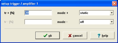 |
It
is possible to choose static or dynamic triggering. You can determine
the
trigger value in percent of the measure range for the static or dynamic
trigger.
Different polarity and mixed trigger mode is also possible.
The preview allows you to control the actual settings. The following
symbols are
used:
| ^ | static trigger positive (the line shows the level) |
| v | static trigger negative (the line shows the level) |
| arrow up | dynamic trigger positive |
| arrow down | dynamic trigger negative |
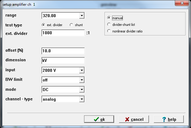 |
In the lower area of the dialog you will find a table with the actual
settings
of the amplifier.
| label | meaning |
| CH | physical channel |
| CH-type | channel-type analog or digital |
| range | measure range |
| dim | dimension ( V,A,etc. ) |
| offset(%) | zero-line in percent of the range |
| mode | input coupling ( AC, DC, GND ) |
| R(in) | input resistance |
| BW limit | bandwith limit |
| divider | divider ratio of external divider |
| input | amplifier input or divider input of measuring system in use |
With
a single click to the desired field you open another dialog which
allows you to
make changes. There are no changes possible if you select a digital
channel
type.
The preview shows the settings of the actual worked channel.
Click to the channel number in column one if you would like to switch
the
preview.
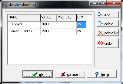
New feature / add-on :
Since software release V2.900 a HV-divider can be defined via a global so-called "divider-shunt list". Each defined divider can be given a name for better recognition and with help of this function Hierzu kann dem Teiler ein Name zugewiesen werden und somit wird es dem Anwender ermöglicht eine etwaige Veränderung des Teilungsverhältnisses mittels einer globalen Änderung für alle damit festgelegten Prüfsetups durchzuführen.
Seit
Softwareversion V2.929 ist nun die Zeitenkorrektur für
Blitzstoß-Teiler
verfügbar interessierenden Kanal umzuschalten. Diese wird
mittels den "Prüfsequenz-Einstellungen" wie folgt aktiviert :
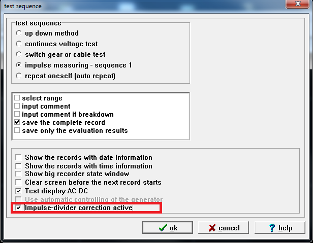
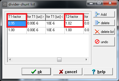
Die Einstellungen für Korrekturfaktoren und deren Gültigkeitsbereich erfolgt über die oben beschriebene "Vorteiler-Shunt Liste" :

This menu item opens a file open dialog which allows you to load recorder settings from your harddisk. The files are labeled with the extension MNU.
This menu item opens a file save dialog which allows you to save actual recorder settings to your harddisk. The extension MNU will be automatically added to the filename.
You will get a selection dialog which allows you to delete files with the extension MNU. Select the file you would like to delete and click the „Open“ button. It is also possible to delete multiple files using the CTRL key while you select the files.
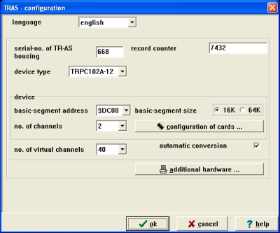 |
All
hardware specific settings will be made in this dialog. Furthermore you
can
change the operation language of the application with the first control
on the
upper left side.
Please make sure that the entry in the field „serial-no. of
measure case“ is
correct. If you are not sure the number is correct contact us!
This number is the key for the identification of the file with the
amplifier
scale factors.
Please
take note that all settings are delivered correctly by Dr. Strauss
GmbH.
Normally you don’t have to make any changes in this dialog!
Only in case of errors you should check these settings and contact us!
If you
make faulty settings the digital recorder will not work correctly!
| label | meaning |
| device type | digital recorder type |
| record counter | record counter of the digital recorder |
| basic-segment address | start-address of the address area which is reserved for the programming and for memory access of the digital - recorder hardware |
| basic-segment size | size of the needed memory area |
| no. of channels | number of physical channels |
| no. of virtual channels | number of additional virtual channels (used for evaluation etc.) |
The
button „configuration of cards...“ starts a further dialog
which provides
controls for the hardware configuration of each physical channel.
The illustrated controls depend on the installed digital recorder type.
Deviations are possible so that some controls are maybe disabled.
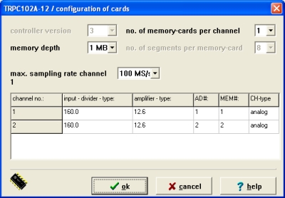 |
controller
- version
This
control is only important for the device type TR100-10 because of
different controller
– versions.
no.
of memory cards per channel
Some
VME-Bus based recorder types allow to operate with multiple
memory-cards per
channel to increase the complete memory depth of the digital recorder.
Normally
this value is set to 1.
memory
depth
Memory
depth means the memory length of one applied memory-card. The complete
memory
depth of the channel results from the number of installed memory cards
multiplied with the memory depth of one memory-card.
no.
of segments per memory - card
The
memory is divided in multiple segments which can be sampled with
different
timbases (see recorder settings!). The number of segments depends on
the selected
device type. It varies from two till eight segments.
clock
- frequency channel 1
This
field determines the quartz frequency of the master channel. Master
channel
means channel no. 1 because this channel provides the quartz controlled
timebase
for all installed physical channels.
The table in the lower area of the dialog shows information about the
installed
input-divider-type, amplifier-type and the addresses of the A/D and
memory card
of each physical channel. You can change these entries with a single
click with
the left mouse button into the desired field of the table.
The button „additional hardware...“ in the main dialog will open a further dialog for the configuration of optional hardware like a DAC16, relay or a PCIO-card.
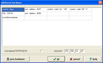 |
The control-relais of our transient-recorder can be programmed with port-address $31F. The control-code for turning on relais is "128", the code to turn off is "0". This control codes can be entered in the above dialogue.
The DAC16-card is used for automatical voltage-control when calibrating recorders / calibrators. This card can be programmed using port-address "$300". This settings can be entered in aboved dialogue.