Primary
the application Transformer Test
must be selected and project must be selected.
| transformer - test - menubar |
If
you have choosen the application “transformer test”, the following menubar
will be displayed.
The most important options and functions will be described in the following
chapter.
 |
The following tables describes all possible options to change.
| Bil 500.00 kV | maximum test-voltage (100%) |
| + / - | positive or negative polarity |
| 30 % | proportional portion of test-voltage |
| terminal | Terminal of test-object |
| standard | Display-view which is loaded while testing |
| reference | Copy to reference channels |
| overlay | standardized comparison |
| compare | standardized comparison with difference channels |
| Tfum | transfer-function (as described below) |
| Tolm | toleranz volume methode (as described below) |
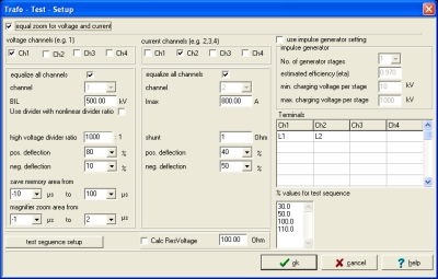
Setting
of the Transformer Setup via Edit/Evaluation/TrafoSetup.
 |
In
this form the Trafo setups with the relevant test parameters must be defined by
create new or modified.
Following Items are important:
The Evaluation mode must be set for each channel used (for LI : LI in K1, PK in
K2, ... for SI : SI in K1, ...)
Setting of voltage channel(s):
BIL and %-values according test specification, polarity negative, offset 90%,
deflection 80%, h.v. divider ratio e.g. 1000 : 1
Settings for current channel(s):
Maximal current magnitude at 100%, offset 50%, deflection 40%, Shunt values e.g.
0,1 - 2 Ohm
Input new Setup-name, e.g. BIL800LI and store with create.
USA
3
| No. | Test with BIL |
| 1 | 50% reduced wave RW |
| 3 | 100% full wave FW |
| 1 | 110% LICfull chopped wave FCW |
in
USA only voltage at LIC evaluated
è
additional LIC- Test - Setup must be defined
Individual intervals for memory area and zoom area can be defined.
| For LI 1,2/50 (0,84/60) | -10
to 100 main zoom -2 bis (4) 8 magnifier |
| for SI 20/4000 | -20
bis (4000) 5000 main zoom -2 bis 40 magnifier |
Europe and Asia
30%
for setup of waves
| No. | Test with BIL |
| 1 | 50% or 62,5% reduced wave RW |
| 3 | 100% full wave FW |
| 1-3 | 100% LICfull chopped wave FCW |
Test
sequence according to test requirements.
Sometimes also LIC reduced chopped wave RCW is applied.
Individual intervals for memory area and zoom area can be defined.
| For LI 1,2/50 (0,84/60) | -10
to 100 main zoom -2 to (4) 8 magnifier |
| for SI 20/4000 | -20
to (4000) 5000 main zoom -2 to 40 magnifier |
- Select
Setup, e.g. BIL800LI
- Set
polarity
- Select
percent value of BIL
 |
Start |
-
50%-wave
à
reference (copy to)
-
additional impulses - Overlay – Compare
- After test: load curve, compare, TFUM, etc.
- Print Test Report / Protocol
- Backup of Project Data:
With help of backup-function or with key Shift F3 in folder
c:\WintrasJob\ProjektName.
Suggestion:
In case the measuring system is connected to a network, the auto-backup path can
be set to the respective server.
In case this path is set to the local harddisk you must consider this while
maintenance of your harddisk. Projects no longer needed should be deleted with
help of the backup-functions.
| manual evaluation modes |
The manual evaluation-types can be used to do special analysis from voltage-current recordings when using transformer-test application. To accomplish a manual evaluation, there must be recorded on impulse, which should be defined as reference. For detailed information please refer to describtion from “channel-copy”.
| overlay |
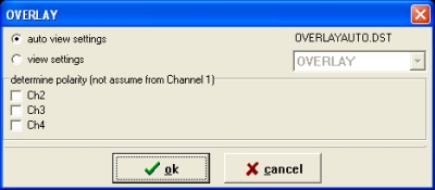
In
this evaluation the reference impulse is standardized to the magnitude of the
measuring impulse. The standardization is done with the record from voltage and
current. After overlay-analysis the corresponding channels of voltage and
current will be displayed together in one system of coordinates.
| compare |
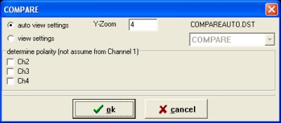
This
evaluation works in the same way as overlay, with the exception that in this
case the graphical difference between reference and measuring impulse is
calculated. The display view of difference-channels will be set with zeroline to
50%, the measuring range is the same as the one of highest measuring range from
reference or measuring record.
After compare-analysis the corresponding channels of voltage and current will be
displayed together in one system of coordinates.
| tfum - transfer function |
 |
With
help from transfer-function you are able to determine the frequency-dependent
conductance of the transformer.
settings
(options) of transfer-function
If you want to
change the settings of the tranfer-function analysis, you must “right-click”
with mouse on the “TFUM”-button from menubar.
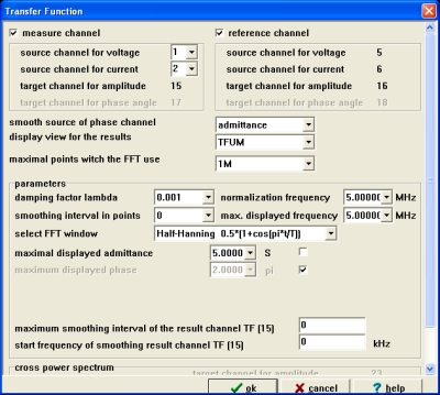 |
The following tables describes all possible options to change.
| measuring channel | channel in which voltage/current has been recorded |
| reference – channel | channel to which reference impulse was copied |
| lambda optimizing | voltage-dependent damp for magnitude |
| norming frequency | frequency window which is
used for sta |
| smoothing interval in points | data of impulse can be smoothed (filtered) with this option |
| fft window | window for boundary value correction |
| maximum displayed conductancy | maximum value of y-scale |
| use coherence function | this option is for checking of evaluation |
| display view for test-setup | here you can select your prefered display-view |
| tolm - tolerance volume methode |
 |
With help of tolerance volume methode you are able to analyse small deviations between special impulses, e.g. this deviations must be determined in quality control some company’s production lines.
settings
of tolerance volume methode
If
you want to change the settings of tolerance volume methode, you must
“right-click” with mouse on the “TOLM” button from menubar.
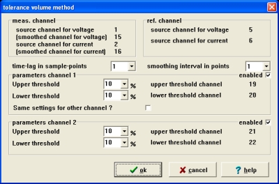 |
The following table describes all possible options to change:
| time-shift (in sampling points) | correction of tolerance method thresholds in the rising section |
| upper threshold of channel 1 | value for upper tolerance border |
| lower threshold of channel 1 | value for lower tolerance border |
| equal settings for channel 2 | the settings of channel 1 will be tranfered to channel 2 |
| smoothing interval in points | data of impulse can be smoothed (filtered) |
| upper threshold of channel 2 | value for upper tolerance border |
| lower threshold of channel 2 | value for lower tolerance border |