compared calibration
The
described programs comparison calibration don’t belong to the usual delivery
of the software. If you have interests or need this parts of the software, you
can purchase them if you contact the manufacturer or your appropriate representative.
For measurements or calibrations corresponding to IEC 1083-1 or IEC 60-2 you
will need high-precision digital recorder For this
assignment there was developed a
whole family of new digital recorder TR-AS including the necessary software,
which give you the ability to practice all claimed calibrations or measurements
corresponding to IEC 1083-1 and IEC 60-2.
The
comarison calibration is a
calibration from a test object with an reference digital recorder.
The calibration of several measuring ranges of digital impulse measurement systems TR-AS 25/8/10/12 or TR-AS 100/200.8/10/12 corresponding to IEC 1083-1 as “performance check”can either be done with an impulse-calibration or alternative with an extra calibration of voltage and time via step-voltage.
The
automatic control of impulse-calibration-systems is done via a coaxial
connection which is connected to the calibration-relay of the digital impulse
measurement system TR-AS.
The channels which you should be calibrated will be connected either alone or in
parallel to the output of the calibration-generator.
ATTENTION : Only
connect outputs while dead.
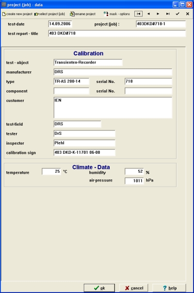
There
must be now an input-dialogue. In this dialogue you can select or create a new
project / job. In this case there is no need to select a test-setup,
display-view or recorder-setting.
Data, which describe the test-object like serial-no., date etc. can be input in
this dialogue.
 |
calibration-type and calibration-profile
 |
Here
you can select the used calibrator-type e.g. KAL1000 and as profile-name the
serial-no. of the used calibration-generator. The input “KAL 1000” without
serial-no. defines a calibrator with standard parameters corresponding to IEC
1082-1. In “calibration-profile” you can input calibration-results of a
calibration-generator. In dependence to the serial-no. e.g. KAL1000#190 you can
additional select the calibrator-settings.
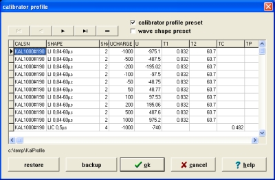 |
Creation
of a calibration-profile
For each
calibration-generator should be generated an own profile. For input of data you
must first select the profile-name. We recommend to use the DKD-calibration
protocol to create a profile and to use as profile-name the “KAL1000”+serial
no. or “DKD”+calibration no.
For each impulse wave-shape you must input the load-voltage and the
corresponding standard values from the calibration-protocol, where the data in
rows with “+” must be input.
impulse
and measuring input
The wave shape and the meas
impulse
- calibration
The impulse calibration is done with the impulse-calibration generator KAL-LI
0,84/60 (optional with KAL-LI 1,56/60) for full or chopped lightning-impulse
waveform or with impulse-calibration generator KAL-SI 20/4000 (optional with
KAL-SI 250/2500) for full or chopped switching impulse waveform. The
corresponding wave shape must be selected.
connection KAL1000-LI and –
SI
If you are using a positive impulse-voltage, there must be connected a
short-circuit plug to the negative BNC-output jack. The positive BNC-output jack
for LI or SI will be connected via a coaxial connection cable with the inputs of
the digital impulse-measuring system which you want to calibrate.
ATTENTION: Only connect outputs while dead.
start of the calibration
/ measurement range
 |
After
starting the calibration with “F8” or the corresponding toolbar button,
there must be made some settings. The recorder can be calibrated in the
measurement ranges with reference to the borders for voltage-range which are
described in the calibration-certificate from KAL 1000. The measurement ranges
which should be calibrated, can be selected with input from the charge
voltage levels.
| start dialog | |
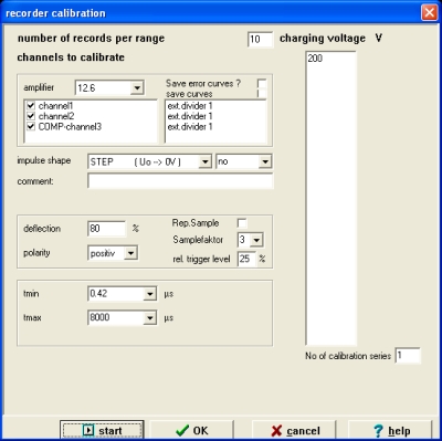
Select for comparison the Comp channel.
The trigger-input of the base-device (firing input) will be connected via
coaxial connection cable with the control-relay output (control out) of the
digital impulse-measuring system.
The amount of the pre-calculated impulse-voltage load will be displayed.
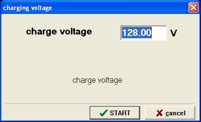 |
The
loading voltage must be chosen corresponding to the reference value at the
calibrator (e.g. KAL1000) or the pre-calculated value of the measuring system must be edited if you
aren’t able to set the value at the KAL 1000.
The
record will be automatically started if you chosen “OK”, the calibration
generator will be triggered and the measured impulse will be evaluated
after this the following input dialog will be opened.
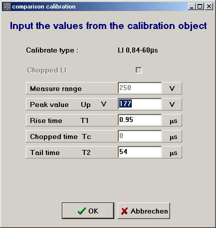
Please put in all values exactly. This will be done until the calibration of the measurement range is ready. If you calibrated a as test object an digital recorder please don't forget the input of the measure range. The values from the reference recorder are used as reference values for the test object.
The calibration is
done after setting the calibration-voltage for all measuring range which you
want calibrated . The preset count of records is done automatically via control-relay of
measurement system. The records will be evaluated corresponding to IEC 1083-1
(e.g. number of records per range 10).
Attention:
For each record please don' t forget input of the test object values. ( e.g. Lightning Impulse Up, T1 and T2 by calibration)
The maximum deviation and the mean-value of the chosen records will be saved
into a protocol-file from which can be made the calibration-certificate later.
The
nominal values are the values from the reference channel (reference
recorder).
At
the beginning of the automatic calibration-sequence, you must input the chosen
value of the loading voltage. This value is the reference for further
calculations in the calibration process.
calibration
with STEP-voltage
This calibration is done with step-voltage taken from the step-voltage generator
KAL-STEP. The wave shape STEP must be selected in this case.
connection
for KAL1000-STEP
For negative STEP-voltage you must connect the BNC-output jack via a coaxial
connection cable with the impulse measuring system you want to calibrate.
ATTENTION: Only connect outputs will dead.
The triggering-input of the KAL1000 base-device (firing input) must be
connected via coaxial connection cable with the control-relay output of the
digital impulse-measuring system. Further information is given in “impulse
calibration”
time
calibration
The time-calibration will be done with a built-in
high-precision time mark-generator. The wave shape TIME must be selected.
connection
for KAL1000-TIME
For the time-calibration the BNC-output jack TIME must be connected via a
coaxial connection cable with the inputs of the digital impulse measuring
system.
The triggering-input of the KAL1000 base-device (firing input) must be connected via coaxial connection cable with the control-relay output (control out) of the digital impulse-measuring system. Further information is given in “impulse calibration”
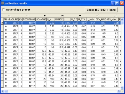
The
calibration results will be saved into the WinTRAS-internal database und can be
displayed in a result list. The automatic IEC-check operation “CHECK IEC
1083-1” displays the maximum differences for each parameter filtered for the
actual wave shape.
In the database and in the protocol are only the values of the test object and the values from the reference channel are used as the nominal values.
 |
First
you can select the wave shapes you want to print.
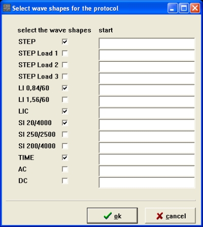 |
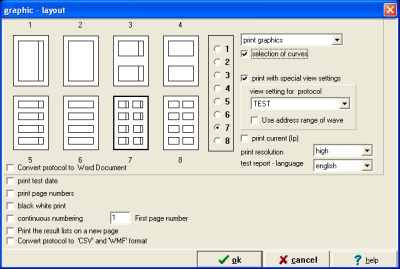
If
you have saved curves when you did your calibration, you can select the output
of this graphics and several other options in this dialogue.
The
output of the calibration results is done in tabular form beginning with the
test-object data and following the calibrated wave shapes (as you can see in the
small preview for the wave shape LI 0,84/60).