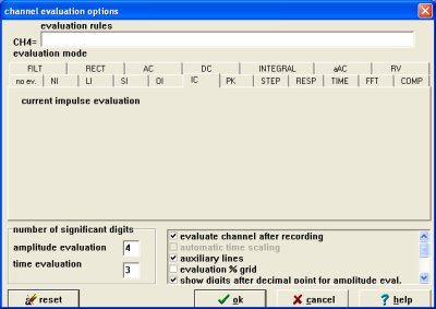
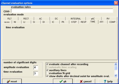
Evaluation modes
The above mentioned evaluations were
developed for the most often used signals and impulse wave shapes,
which exist in
measuring technique.
In the majority of cases this evaluations can only be used for the
waveform corresponding evaluation was develop for.
Below are descriptions of all available evaluation modes with its
tasks,
characteristics and settings.
These evaluations are in conformity to valid IEC, DIN and IEEE
regulations.
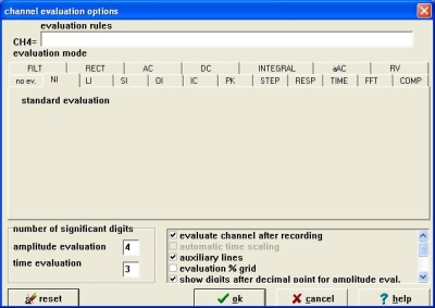 |
The standard
evaluation analyzes and shows in all cases peak value (Up),
front time
(T1) and, if chopped wave, the chopping time (Tc).
This evaluation has no specific settings.
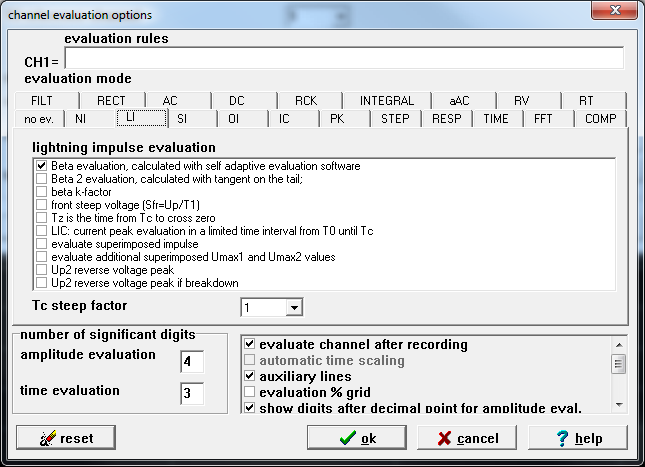 |
For the lightning
impulse evaluation there are for full waves the front time (T1),
time-to-half value (T2) and peak value (Up)
which will be
evaluated and shown.
For chopped waves the time-to-chop (Tc)
will
be calculated instead of time-to half values (T2).
Following settings can be adjusted :
- If beta-evaluation is checked, the overshoot
behavior according
to IEC 60060-1 is evaluated (according to standard's
definition of editions before Edt.3)
- If beta2-evaluation is checked, overshoot behavior
is evaluated via reverse calculation of best fitting tangent within
tail
(refer to link Beta 2 Evaluation (overshoot) and corresponding description)
- If beta k-factor is checked, complete lightning
evaluation will take
place according to IEC 60060-1 Edt. 3 (this affects complete peak and
time parameter
results)
- front-steepness : steepness between 30% and
90% values is
acquired
- time-to-zero
calculation
- limitation of current peak : only search within
time range between virtual origin (T0) and chopping time (Tc)
- evaluation of superimposed impulses
The steep factor is
important for the correct recognition of chopped
waves. For example if steep factor =1, then steepness at chopping-time
Tc
has to at least be as high as the steepness within the rise of the
impulse voltage.
Evaluation of
Impulse Parameters for
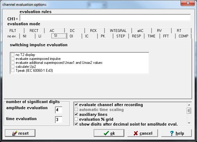 |
In switching
impulse evaluation the value of peak (Up) is determined.
The time (Tp) is from the beginning time T0
until T100 (peak) and
the "duration" time (Td) is rated between 90%
values of front and tail of the underlying impulse.
If the voltage of the wave shape reaches again the zero line level
0% then additional the time-to-zero (Tz) is shown.
Options : no T2 display
calculate Up2 (percentage value in respect to Up)
New : Time-to-Peak Tp acc. to IEC 60060-1 Edt. 3
|
 |
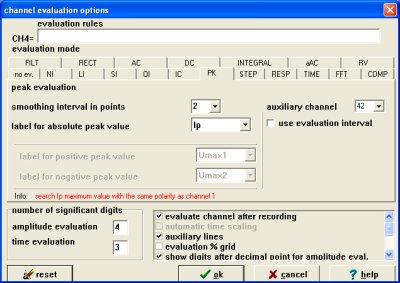 |
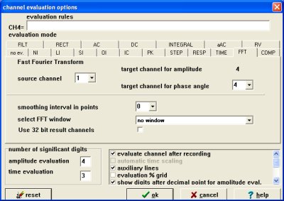
New : smoothing inverval in points, auxiliary channel
 |
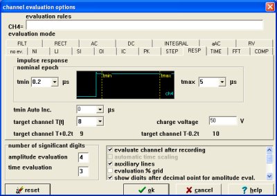 |
target channel T(t) = 8
target channel 1+0.2*t = 9
target channel 1-0.2*t = 10
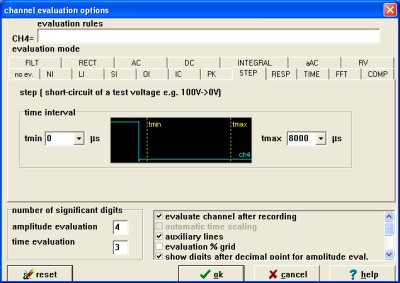
tmin and tmax are the evaluation interval. Tmin auto increment is a specially function to find the shortest settling time (Ts).
|
| FFT - fast fourier transformation |
 |
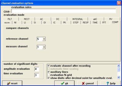
| Comp - compare channels |
 |
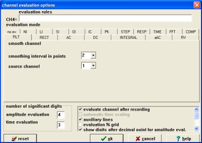
| Filt - smooth channel |
 |
| Rect - rectangular evaluation |
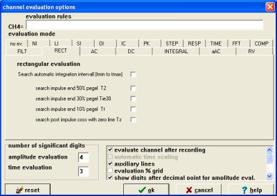 |
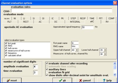
| AC - AC - evaluation |
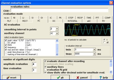 |
New: the evaluation works now from tmin to tmax. The zero-time refers to the time of trigger event (point). It is possible to select a value from the list or input your own values.
New : peak time phase - op (Tp)
marking of time interval (timemark)
| DC - DC - evaluation |
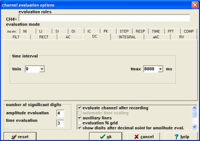 |
The evaluation works from tmin to tmax. The zero-time refers to the time of trigger event (point). It is possible to select a value from the list or input your own values.
 |
|
|